
Consider a company that has users in several buildings in a campus network. Building A has four floors, and building B has two floors, with the address requirements shown in Table 1-28.
Table 1-28 Building Address Requirements
| Network Location | Addresses Required |
| Building A: Floor 1 | 40 |
| Building A: Floor 2 | 70 |
| Building A: Floor 3 | 30 |
| Building A: Floor 4 | 90 |
| Building B: Floor 1 | 80 |
| Building B: Floor 2 | 120 |
As shown in Figure 1-7, the building’s Layer 3 switches will be connected via a dual-fiber link between switch A and switch B. Both switches will connect to the WAN router R1. Assume that you have been allocated network 10.10.0.0/17 for this campus and that IP phones will be used.
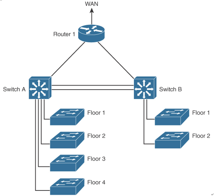
Figure 1-7 Campus Network Connectivity
Many possible solutions meet the requirements for IPv4 address assignment. Table 1-29 shows one solution.
Table 1-29 Building IPv4 Address Allocation
| Network Location | Addresses Required | Subnet Size | VLANs | Addresses Assigned |
| Building A: Floor 1 | 40 | /24 | 11 | 10.10.11.0/24 |
| Building A: Floor 2 | 70 | /24 | 12 | 10.10.12.0/24 |
| Building A: Floor 3 | 30 | /24 | 13 | 10.10.13.0/24 |
| Building A: Floor 4 | 90 | /24 | 14 | 10.10.14.0/24 |
| Building B: Floor 1 | 80 | /24 | 21 | 10.10.21.0/24 |
| Building B: Floor 2 | 120 | /24 | 22 | 10.10.22.0/24 |
| Switch A–switch B links | /30 | 10.10.2.4/30 and 10.10.2.8/30 | ||
| Switch A R1 link | /30 | 10.10.2.12/30 | ||
| Switch B R1 link | /30 | 10.10.2.16/30 | ||
| R1 loopback | /32 | 10.10.1.1/32 | ||
| Switch A loopback | /32 | 10.10.1.2/32 | ||
| Switch B loopback | /32 | 10.10.1.4/32 | ||
| Building A: Floor 1 IPT | 40 | /24 | 111 | 10.10.111.0/24 |
| Building A: Floor 2 IPT | 70 | /24 | 112 | 10.10.112.0/24 |
| Building A: Floor 3 IPT | 30 | /24 | 113 | 10.10.113.0/24 |
| Building A: Floor 4 IPT | 90 | /24 | 114 | 10.10.114.0/24 |
| Building B: Floor 1 | 80 | /24 | 121 | 10.10.121.0/24 |
| Building B: Floor 2 | 120 | /24 | 122 | 10.10.122.0/24 |
| Access control system | 40 | /24 | 300 | 10.10.3.0/24 |
Data subnets are assigned starting with IP subnet 10.10.11.0/24 for floor 1 in building A. Notice that the VLAN number matches the third octet of the IP subnet. The second floor is assigned VLAN 12 and IP subnet 10.10.12.0/24. For building B, VLAN numbers in the 20s are used, with floor 1 having a VLAN of 21 assigned with IP subnet 10.10.21.0/24.
VLANs for IP telephony (IPT) are similar to data VLANs, with the correlation of using numbers in the 100s. For example, floor 1 of building A uses VLAN 11 for data and VLAN 111 for voice, and the corresponding IP subnets are 10.10.11.0/24 (data) and 10.10.111.0.24 (voice). This approach is repeated for all floors.
This solution uses /30 subnets for point-to-point links from the 10.10.2.0/24 subnet. Loopback addresses are taken from the 10.10.1.0/24 network starting with 10.10.1.1/32 for the WAN router. Subnet 10.10.3.0/24 is reserved for the building access control system.